Call us
08045805152

TECHNICAL SPECIFICATIONS
| DGA Method: Solid-state H2 sensor immersed directly in the oil | Hydrogen (H2 ) | Accuracy | Repeatability | Range |
|
| 15% or 20 ppm | 5% or 10 ppm | 20 10,000 ppm | |
|
| 1) Lower Detection Limit 20 ppm |
|
| |
| Additional Monitoring Options (Optional) |
| Accuracy |
| Range |
|
| Moisture-in-Oil | 5% |
| 0-100% RS |
|
| Oil Temperature | 2C (typically) |
| -40C to +120C |
| Gas Analysis Parameters | Oil Sampling Rate | Continuous oil sampling; gas analysis is reported every 30 minutes | ||
|
| Data Management | Data is date and time stamped; up to five years of data is stored in memory | ||
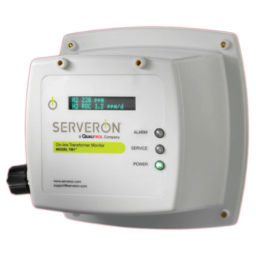
| Display | Integrated display of H2 Level, H2 Rate of Change (ROC), Moisture (optional) and Service Codes. | |||
| Alarms | Relay Contact Ratings | Max switched Power 100 W or 600 VA, Max switched Current 3 A, Max switched Voltage 150 VDC or 300 VAC | ||
|
| 3 DGA Relays | Three (3) programmable alarm relays for H2 Level (ppm), H2 Rate of Change (ROC) (ppm/day), and optional Moisture | ||
|
| 2 Alarm Relay | Two (2) alarm relays for power and service status | ||
| External Inputs | Digital Inputs | RS232 for configuration utility and diagnostics; USB Mini B for direct connection with computer or USB Thumb Drive | ||
|
| Analog Inputs | Two (2) analog 4-20 mA inputs for optional moisture probe | ||
| Communications | Standard Interfaces | RS232 / 485, USB 2.0, Three (3) analog 4-20 mA outputs for H Level, H 2 2 Rate of Change (ROC) and optional Moisture | ||
|
| Supported Protocols | DNP3 and Modbus | ||
| Environmental Specifications | Operating Temperature | -50C to +55C |
|
|
|
| Oil Temperature | -20C to +105C |
|
|
|
| Oil Inlet Pressure | 0 to 100 psi (0 to 7 bar) |
|
|
| Physical Specifications | Product Dimensions | HxWxD: 9.2 in x 9.9 in x 12.3 in (23.4 cm x 25.1 cm x 31.2 cm) | ||
|
| Product Weight | 9 lb (4 kg) | ||
|
| Enclosure Rating | NEMA 4X, IP66 | ||
| Input Power Requirements | Voltage | 100 - 240 VAC |
|
|
|
| Frequency | 50/60 Hz |
|
|
|
| Current | 0.8 A max. |
|
|
| Radiated and Conducted Emissions | Radiated Emissions | EN 61326-1: 2006 |
| CISPR 11: 2009 A1: 2010 Class A |
|
| Conducted Emissions | EN 61326-1: 2006 |
| CISPR 11: 2009 A1: 2010 Class A |
|
| Current Harmonics | EN 61000-3-2: 2006 A1: 2009 A |
| EN 61000-3-2: 2006 A1: 2009 Class A |
|
| Voltage Fluctuations | EN 61000-3-3: 2008 |
| EN 61000-3-3: 2008 Class A |
| Radiated and Conducted Immunity | ESD | EN 61326-1: 2006 |
| IEC61000-4-2: 2009 |
|
| Radiated Immunity | EN 61326-1: 2006 |
| IEC61000-4-3: 2006 A2: 2010 |
|
| EFT | EN 61326-1: 2006 |
| IEC61000-4-4: 2004 A1: 2010 |
|
| Surge | EN 61326-1: 2006 |
| IEC61000-4-5: 2006 |
|
| Conducted RF Immunity | EN 61326-1: 2006 |
| IEC61000-4-6: 2009 |
|
| Magnetic Field Immunity | EN 61326-1: 2006 |
| IEC61000-4-8: 2010 |
|
| Voltage Dips & Interrupts | EN 61326-1: 2006 |
| IEC61000-4-11: 2004 |
|
|
| IEC 60255-21-1 |
|
|
| Safety |
| IEC 61010-1 |
|
|
|
|
| IEC 61010-2-81 |
|
|
|
|
| UL 61010-1 (2nd Edition) |
|
|
|
|
| CSA-C22.2 No. 61010-1-04 |
|
|

Price: